This page describes the assembly of the hvps-x PCB in a 3D-printed enclosure for added protection and safety.

For additional safety and protection, we recommend placing the PCB inside a box/enclosure. You can find STL files for a 3D printed box on the download page. The box has two parts: a bottom (image above, left) and a top (right). In addition to printing the two parts, you will need a few components, listed below. Components indicated in BOM file are located on the tab “Cables_connectors_and_accessories” of the BOM.
- 5x M3x4.2OD x5mm (or 5.5mm) inserts such as this (Use a soldering iron to heat them and push them in the PLA enclosure). Not in BOM file.
- 4x M3x12mm screws hex socket cap. Not in BOM file
- 1x M3x5mm screw hex socket cap. Not in BOM file
- 1x Ring terminal. In BOM file
- 1x Grounding wire. In BOM file
- 1x Push button. In BOM file
- 2x LED pipe. In BOM file
- 1x short Female-Female Dupont wire. Not in BOM file
Assembling the 3D-printed protection enclosure
Bottom part of the enclosure
- Using heat (e.g. with a soldering iron) push one of the M3 insert into the hole in the bottom surface aligned with the rectangular opening
- Place your hvps-x PCB in the enclosure. Insert the side with the output connectors first and then lower the side with the jack/button/usb connector.
- Prepare your grounding wire by crimping or soldering the grounding wire to the ring terminal. Place the most convenient connector on the other end of the cable, depending on how you can connect to earth ground. It can be a 4mm banana plug, if you have an earther banana socket on your workbench. If you are using this kind of plugs that connect to mains, then you can use another ring terminal of the proper side for the screw. This is up to you and the configuration of your bench, but for safety, the ground reference of the hvps-x should be connected to Earth ground.
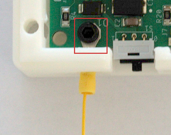
- Slide the ring terminal through the square hole in the enclosure and use a M3x5mm screw to tighten the ring connector and PCBA to the bottom of the box (see figure inset above).
- Connect the other side of the grounding wire to a good earth ground point.
Top part
- Using heat, push 4 M3 inserts into the mounting holes on the side
- Insert the two LED light pipes into the small holes. You may need to use a small hammer to fully insert them.
- Cut the female-female Dupont wire in two. Solder the side without connector to the push button. Add some heat-shrink tube on the solder joints (not shown on the picture)
- Place the nut of the button into the recess on the back side and screw the button from the front side.
Assembly
- Connect the female connectors of the Dupont wires to 2-pin header J11.
- Place the cover on top of the bottom part with PCBA.
- From the backside, secure the two parts together with 4 M3x12mm screws.

Now that your high-voltage power supply is well protected, you can
- Use it with the Python GUI
- Calibrate your hvps-x to have accurate output readings
Enclosure CAD source file
The enclosure is designed with OnShape, which is free for personal use (all documents are public), and also offers a free academic license. If you have an OnShape account, you can clone the project and modify it to suit your needs.
There are tabs at the bottom of the window: one for the bottom part, and one for the top part (cover).