Although not absolutely necessary, we recommend testing the communication with the micro-controller once you have finished the first assembly step (soldering the SMT/SMD components). This enables you to confirm that the USB connector and the micro-controller are correctly soldered before continuing with the assembly. Indeed you wouldn’t want to spend time and money soldering new components, if the core of the system is not functional.
What you need
- A power supply that can generate 3.3 V. If you have an Analog Discovery 2 at hand, you can use its programmable power supply instrument.
- A USB cable with a USB micro plug
- The STM32CubeProgrammer software, which you can download from ST.
- The hvps-x firmware (.hex file), which you can get from the Download page.
How to proceed
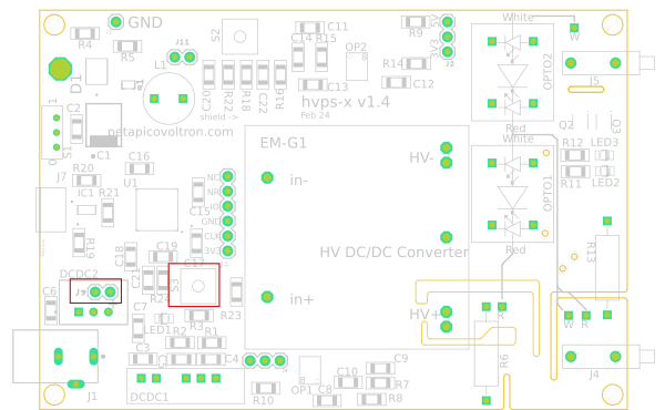
- Solder temporary wires (they will be removed later) to two pads named J9 found inside the footprint of DCDC2. Ground is on the left and +3.3V is on the right (indicated with + on the silkscreen)

- Connect the wires to the 3.3V supply. Make sure to respect polarity (Ground is on the left and +3.3V is on the right (indicated with + on the silkscreen). Do not turn on voltage at this stage
- Press the Boot push-button (S3) and keep it pressed
- With the Boot button down, turn on the 3.3V power supply. You can release the boot button now.
- Connect the USB cable to your computer and to the hvps-x.
- Check that the Microcontroller appears in the device manager as a STM32 BOOTLOADER
 If it doesn’t, something is not working properly.
- Check that the board is powered with 3.3V. You can probe the voltage on one of the 2 upper pins of S3; they are connected to the 3.3V net
- Make sure the boot button is working properly (sometimes these on-chip buttons are borderline temperamental): Probe the voltage on one of the bottom pins of S3. It should be 0V when the switch is not pressed, and 3.3V when it is pressed.
- Try the procedure again: disconnect the usb plug and turn the voltage off. Press Boot, turn the voltage on while holding Boot pressed, release Boot, insert USB cable
- If still not working check the soldering of J7, IC1, and U1. They have fine-pitched packages and can be difficult to solder correctly.
- Launch STM32CubeProgrammer
- On the right-hand side of the screen, select USB. If port indicates “no device detected” use the refresh button. If the device manager shows the STM32 Bootloader device, it should be correctly detected at this stage.

- Click ‘Connect’. The left part of the window will show the current content of the memory, which should be 0 everywhere. The bottom of the RHS menu will give information on the micro-controller.

- At the top of the window, select the tab ‘Open File’ and browse to the .hex file of the hvps-x firmware
- Press the button ‘Download’ to send the programme to the micro-controller

- A message ‘File download complete’ will be displayed at the end of the process.
- Optionally, once it is done, you can click on the down arrow of the download button and choose ‘Verify’. This will check that the content of the micro-controller’s memory matches the loaded file.
- Click on disconnect and close the CubeProgrammer.
- Power cycle the device by turning off the 3.3V supply and then back on.
- On power-up, the board should now appear in the device manager as a communication port:

- Run the Python library as a main script from the folder in which you saved the library:
-
python hvps_lib.py
- Alternatively, if using windows, you can use the compiled executable hvps_lib.exe in the same folder as the interface main executable.
- Once the programme is launched and the hvps-x detected, use the option [1] Initial configuration (to be performed after assembling the low-voltage components). This will save some parameters in memory that will be useful for the upcoming tests. See output below. Red are user inputs.
Your choices:
[1] Initial configuration (to be performed after assembling the low-voltage components)
[2] Basic functionality test (to be performed after assembling the high-voltage components)
[q] quit

Your choice: 1
Is the hvps-x (U)nipolar or (B)ipolar? U
Setting configuration
Enter the version of your hvps-x PCB (hardware version), as printed on the PCB (format: X.Y; e.g. 1.2): 1.2
The current name of the hvps-x is Kraken
Do you want to set/change the name of this hvps-x? (Y)/(N)?Y
Enter hvps-x name (12 char max): Gamma

The current maximal voltage rating of this HVPS is 5000 V
Do you want to set the maximal voltage of the HVPS? (Y)/(N)Y
Enter the maximal voltage of the hvps-x in Volt. It must match the voltage rating of the Emco DC/DC converter:5000
Setting Vmax to 5000V
Default values for this voltage found in configuration file

Do you want to replace the values stored in the hvps-x by the one from the config file (Y/N) (choose Y if configuring a new hvps-x)Y
Voltage calibration values set...

Reset PID values to their default values? (Y)/(N) (choose (Y) when configuring a board for the first time)Y
PID values set...

hvps-x configured. It is recommended to perform a calibration of the voltage readout circuit!
Saving information to hvps-x memory. Backup-settings and default settings
-
- Remove power to the board and de-solder the temporary 3.3V cables you soldered to J9. J9 won’t be used for anything else, so it doesn’t matter if solder remains in the hole.


Next step
Once you have checked the the microcontroller and the USB communication are working as expected, it is time to assemble the low-voltage through-hole components.