Let’s check that things are working correctly before we solder the costly high-voltage components.

- With a multimeter, measure the input resistance of the +13.5V input; between GND and +13.5V (the bottom leg of switch S1), and make sure there is no short-circuits. The resistance will depend on the multimeter used and will likely be drifting, but it should be >10 kΩ.
- Make sure that the power supply you are using is +13.5V DC (12Vto 15V OK), and that the positive terminal is on the inside of the barrel plug. Check a second time to make sure, as there is no overvoltage or reverse polarity protection on the board input. If you are using the power supply listed in the BOM (tab accessories), you don’t need to check this.
- Make sure that switch S1 is in position 0
- Plug your power supply to the board. If all is going well, LED1 should be on (green). If not, make sure the plug is fully pressed into the jack. There is a first step with some resistance but you need to push it fully inside.
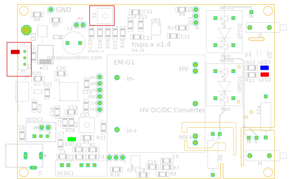
- With a voltmeter, measure the following voltages with respect to GND (the picture above shows where they are accessible). Confirm that you have the correct voltages.
- +13.5V
- +5V (can be +4.5V, as long as >4V, you are good). This net can be measured on the right hand side of either R4 or C4 (see picture above)
- -5V (can be -4.5V, as long as <-4V, you are good). This net can be measured on the left pin of header J6. You will have to remove the jumper to do so.
- +3.3V
- If you skipped the communication test / initial configuration after soldering the SMT components, now is the time to do it. Part of the procedure involves downloading the firmware to the micro-controller, and saving some configuration parameters to the EEPROM. If you have already performed these step, skip to the next test.
- Place switch S1 on the 1 position
- Press switch S2 and keep it pressed. LED 2 (red) should turn on
- Release switch S2. LED 2 should turn off and LED 3 (blue) should turn on
- Put switch S1 back to position 0. LED2 and LED3 should be off
- Remove power from the hvps-x
Next step
Is everything working up to now? If yes, let’s solder the high voltage components.