This page describes how to calibrate the high voltage power supply. There are two calibrations that should be done:
The default settings included in the firmware contains default calibration values for voltage and current calibration thus ensuring that the power supply will behave decently out of the box. However, more accurate voltage readings and better waveform control can be achieved if the power supply is properly calibrated.
1 Voltage calibration
1.1 Why voltage calibration?
Proper calibration of the hvps-x provides an output error lower than +/- 0.3% of full scale (+/- 15V for a 5kv unit).
The hvps-x reads the output voltage at two locations: at the output of the high voltage DC-DC converter and at the output of the terminal of the power supply. Internally, the hvps-x reads voltage as a 12-bit value, i.e. a number between 0 and 4095. We need to define a function that converts this number into a calibrated voltage. In an ideal case, this function is a simple first order polynomial, but some non-linearities always exist. Hence, the hvps-x provides 3 calibration methods:
- Linear calibration
- Quadratic calibration
- Linear interpolation
1.2 Default calibration values
When you perform the initial configuration as part of the assembly step testing communication with the micro-controller, default calibration values are transferred to the hvps-x. These values are based on the nominal resistor values that are part of the measurement circuit. As real components have tolerances, these default values represent a good guess, but won’t give you the most precise output voltage. The voltage readout circuitry is based on a voltage divider. The tolerance of the resistors used for the measurement divider is +/-1%, thus leading to a tolerance on the voltage reading of +/- 2%. Additional uncertainty can be introduced by the buffer and analogue-to-digital converter. Depending on the requirements for your application, you may want to perform a calibration of the hvps-x and replace the default calibration values by values that are specific to your hvps-x.
The default calibration values are defined in the file config.php.
1.3 Calibration examples

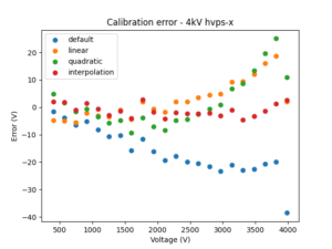
The graph on the right shows a calibration example on a 4kV power supply.
- Blue represents the default calibration values (linear calibration) provided in the config.ini file for a 4 kV unit. The maximum absolute error 38.9 V and the mean absolute error over the whole measurement range is 16.3 V
- Orange represents a linear calibration. This is the same type of equation as for the previous case, but polynomial constants specific to this board were calculated by preforming a least square regression on measured output voltage data. With this, the absolute maximum error is 18.8 V, and the man absolute error is 5.36 V, i.e. a significant improvement compared to the default calibration.
- Green is a quadratic calibration. The same experimental data is used, but it is fitted to a second order polynomial. In this case, the absolute maximum error is 25.1 V, and the mean absolute error is 6.75 V. Quadratic calibration wouldn’t be a good choice for this particular unit.
- Red is linear interpolation: the measurement points are transferred to the hvps-x and used as a lookup table, using linear interpolation to estimate the voltage between two measurement points. For this method, the maximum absolute error is 4.53 V, and the mean absolute error is 2.26 V
| Calibration method | Maximum absolute error | Mean absolute error |
|---|---|---|
| Default | 38.5 V | 16.3 V |
| Linear | 18.8 V | 5.36 V |
| Quadratic | 25.1 V | 6.75 V |
| Interpolation | 4.53 V | 2.26 V |
For this 4kV unit, the interpolation calibration method provides a substantial improvement compared to the default method highlighting the benefit of performing a unit-specific calibration to ensure a good accuracy of the output voltage.

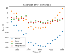
The graph on the right shows the same data for another hvps-x (this one a 5 kV unit), with error statistics summarised in the table. For this case, the best calibration would be the quadratic calibration.
For both of these examples, replacing the default calibration by the best calibration using measurement data improve the mean absolute error by a factor of 7, and to a value below 3 V. This is smaller than 1/1000 of the full scale output voltage of the power supply.
| Calibration method | Maximum absolute error | Mean absolute error |
|---|---|---|
| Default | 28.9 V | 20.3 V |
| Linear | 11.5 V | 6.02 V |
| Quadratic | 5.35 V | 2.91 V |
| Interpolation | 5.70 V | 2.93 V |
1.4 How to calibrate the high voltage power supply?
You need a high voltage probe to calibrate the high voltage power supply. When performing a calibration, we measure DC voltage, and a probe that connects to a multimeter, such as PR28A works well. Another alternative is to use an oscilloscope and a probe capable of measuring dynamic signals. This will allow you to also measured the output waveform in switching mode. PR-55 is a good dynamic probe, but there’s a noticeable price difference. For voltage calibration, the first probe is all you need, but just keep in mind that you cannot use it for dynamic measurements.

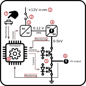
As shown on the image above, the voltage is measured at two different locations (highlighted monitoring arrow):
- at the output of the EMCO DC-DC converter. Keeping a future bipolar hvps-x in mind, the monitoring at location (4) is a positive voltage, and in the firmware, this is referred to the positive, or p calibration.
- At the output of the hvps-x, location (6). This is referred to the output, or o calibration
1.4.1 Calibrate the high voltage power supply with a polynomial calibration
To calibrate the high voltage power supply with a polynomial calibration (either linear or quadratic), you need to to find the coefficients C of the equation y = C0+C1 x (for a linear calibration), or y = C0+C1 x + C2 x² (for a quadratic calibration), where x is the value read by the hvps-x ADC (analogue-to-digital converter), and y is the real voltage value read by the high voltage probe. For a linear calibration, you will need to measure at least 2 points, and for a quadratic calibration, you will need at least 3 points, but you will get much better results if you measure more points evenly spread between 0V and the maximal voltage output. We usually take 21 measurement points for our calibrations.
Currently, you need to use the Python library to calibrate the high voltage power supply. Refer to the Python library page to get started.
- Connect your high voltage probe to the output of the hvps-x and to a voltmeter or oscilloscope, depending on the type of probe that you are using.
- Set the voltage mode of the hvps-x to open-loop mode as it is a bit less noisy.
- Set the switching source on ‘Timer’ so that you don’t need to press the button to activate the output.
- Set the switching mode to ‘high’ to connect the high voltage DC-DC converter to the output, so that you can measure the voltage with your probe.
- Set the voltage to a value (we suggest you start with 0).
- Read the raw ADC reading using the voltage q_vnow_raw(). This function returns two ADC values. The first one represents the voltage at the output of the DC-DC converter and the second represents the voltage at the output of the hvps-x.
- Go back two steps and set a voltage that is a bit higher and continue until you reach the maximal voltage

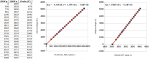
You should end up with a table with 3 columns, as shown in the figure above on the left. The first column is the ADC value from the DC-DC converter (p), the second column is the ADC value for the output (o) of the hvps-x, and the 3rd column is the voltage in volts measured by the high voltage probe. Make two graphs, one by plotting the output voltage wrt the ADC value of the high-voltage DC-DC converter (centre) and a second one with the output voltage wrt the ADC value of the hvps-x’s output (right). For each graph, fit a polynomial of order 1 (line) or 2 (parabola) depending on the order of the calibration that you want. The figure above shows an example of quadratic calibration of the output of the DC-DC converter, and linear calibration for the hvps-x output. You should end up with 3 calibration coefficients for each graphs representing the coefficients of the polynomial Vout = C0 + C1 ADC_value + C2 ADC_value²
A few important points:
- If you decide to use a linear calibration, coefficient C2=0
- If you decide to use a quadratic calibration, coefficient C2 should be very small. Visually, the measurements points of the centre graph appear linear. The quadratic terms represents a very small non-linearity.
- The coefficient C0 of the DC-DC converter output should be very small (ideally 0).
- The coefficient C0 of the hvps-x output should be close to -1 times the voltage rating of the hvps-x. For example, one would expect -5000 V for a 5kV hvps-x, and we can see that the value identified by the least square fitting is -5230 V. This is because this measurement is designed to handled a voltage swing between +/- the absolute maximum, which will be used for the future bipolar unit.
Transferring the calibration coefficients to the hvps-x
From the Python console, after connecting to the hvps-x (refer to the Python library page to get started), use the function
s_cal(val, calibration_constant)
where val is the value of the calibration constant and calibration constant describes which of the 6 calibration constants should be assigned the value val. There are 6 calibration constants, because there are two voltage readings to calibrate, and each require 3 constants. calibration_constant is one of the 6 CAL_CXY, with X={0,1,2} for the calibration coefficient of order X, and Y={P,O}, for positive voltage measurement, or output voltage measurement. Once the calibration constants are transferred to the hvps-x, they need to be saved in the non-volatile memory as default settings and backup settings (refer to the page on memory and settings).
Taking the examples values from the figure above, here is the whole process in the Python console. You first want to power-cycle the hvps-x to make sure that the default settings are transferred to the active settings in RAM. This ensures that when you save the state of the hvps-x, the only values that will change are the calibration constants.
import hvps_lib as h
dev=connect_to_hvps()
dev.s_cal(-7.83, h.CAL_C0P)
dev.s_cal(1.27, h.CAL_C1P)
dev.s_cal(-5.47E-6, h.CAL_C2P)
dev.s_cal(-5230, h.CAL_C0O)
dev.s_cal(2.55, h.CAL_C1O)
dev.s_cal(0, h.CAL_C2O)
s_calibration_method(which=VNOW_POS, calmeth=h.CALMETH_POLYNOMIAL)
s_calibration_method(which=VNOW_OUT, calmeth=h.CALMETH_POLYNOMIAL)
dev.s_settings(h.SETTINGS_BACKUP)
dev.save()
dev.s_settings(h.SETTINGS_CURRENT)
dev.save()
dev.close()
1.4.2 Calibrate the high voltage power supply with interpolation calibration
If you want to calibrate the high voltage power supply with interpolation calibration, you need to transfer the values from your measurement table to the hvps-x. The interpolation needs 21 points. For best results, the 21 points are spread evenly between 0V and the maximal voltage. For interpolation to work correctly, it is important that the lookup table includes the complete range of values that can be encountered when the hvps-x is used. This means that the first point must be for a 0V voltage set point, and the last point must be slightly higher than the maximum output of the hvps-x. This is possible, as the calibration is made in open-loop, and voltages up to 10% higher than the voltage rating.
To upload a point of the lookup table to the hvps-x, use the function s_lookup(value, index, lookup_table), where value is the value of the point to transfer, index is the index of the point in the array (0-20), and lookup_table defines which lookup-table the point should be added to. It takes the following values:
- LOOKUP_ADC_P, for the ADC values of the high voltage DC-DC converter output
- LOOKUP_ADC_O, for the ADC values of the hvps-x output
- LOOKUP_VOUT, for the voltage values measured with the probe.
For example, assuming that the lookup values are in three 21-element arrays ADC_p, ADC_o, and Vout, you can use the following code:
import hvps_lib as h
dev=connect_to_hvps()
for index in range(21):
    dev.s_lookup(ADC_p[index], index, h.LOOKUP_ADC_P)
    dev.s_lookup(ADC_o[index], index, h.LOOKUP_ADC_O)
    dev.s_lookup(Vout[index], index, h.LOOKUP_VOUT)
s_calibration_method(which=VNOW_POS, calmeth=h.CALMETH_LOOKUP)
s_calibration_method(which=VNOW_OUT, calmeth=h.CALMETH_LOOKUP)
dev.s_settings(h.SETTINGS_BACKUP)
dev.save()
dev.s_settings(h.SETTINGS_CURRENT)
dev.save()
dev.close()
1.4.3 Combining calibration methods
You can calibrate the high voltage power supply with a different method for the DC-DC converter and hvps-x output; they don’t need to use the same method. You can also transfer both the polynomial calibration coefficients and the lookup table to the hvps-x. Then you can easily choose which calibration to use with the command
s_calibration_method(which, calmeth)
where which represents which calibration you want to set (VNOW_POS or VNOW_OUT), and calmeth is the calibration method to apply (CALMETH_LOOKUP or CALMETH_POLYNOMIAL). Don’t forget to use the save command if you want to make that change permanent. A save() alone will save the current active settings as current settings. Use the s_settings() function to force saving to the backup settings.
You can check the calibration method used for the current settings in the GUI by clicking the Memory button. It will show the calibration method and polynomial coefficients. The lookup table is not displayed in the dialog box, but will be present if you dump the memory into a JSON file. See the GUI user manual.
2 Current calibration
2.1 Why current calibration
The waveform mode relies on a PID controller to produce a custom high-voltage waveform. The values of the PID controller depend on the HVPS-x output current. The GUI includes a machine-learning algorithm to calculate optimal gains Kp (the proportional element of the PID controller) and Ki (the integral element). This machine-learning algorithm relies on knowing the output current of the hvps-x to provide good gains suggestions for the PID.
Default values are programmed in the hvps-x, but if you have the equipment to measure the output current, we recommend you do so.
2.2 Measuring the output current
To perform the measurement, you will need a high-bandwidth high-voltage probe (high-bandwidth is not really required, but a DC probe for voltmeters will probably not work). We use a Testec HVP-15HF. You also need an oscilloscope. We use an Analog Discovery 3. You will also need a high voltage capacitor with a voltage rating higher than the output voltage of your hvps-x, and ideally around 500-1000 pF.
- Connect the capacitor to the output of the power supply and connect the high voltage probe in parallel with the capacitor
- Launch the GUI and configure the hvps-x in switching mode with a frequency of a few Hz (e.g. 5), and to the full amplitude of the hvps-x
- Set your oscilloscope to display the waveform. Set the time and voltage scale to see the first few milliseconds of a rising edge: when charging a capacitor, the current is proportional to the slope of the voltage versus time. But as part of the current is sunk into the probe, we need to check the slope when the voltage is ~0V, i.e. when the current lost in the probe can be neglected.
- Use the cursors of the scope, to measure the change of voltage over a small amount of time near the beginning of the step. In the example below, we measure the voltage change for over a time of 1ms: 244mV on the scope, but 244V in reality, as the probe as a 1:1000 attenuation factor. We therefore have a charging slope of 244V/ms = 244000 V/s. The load in this case is a 680pF capacitor.

- The equation to calculate the current is

- You can repeat the measurement with the current selection jumper (J2) in the second position to measure the current in normal and high current mode.
2.3 Transferring the measured current to the hvps-x
There are 2 ways of transferring the current values to the hvps-x. You can launch the initial calibration script, which is part of the hvps-lib.py library, similar to what you did when you configured the hvps-x for the first time (c.f. Testing communication with the micro-controller.) The script will tell you that the hvps-x is already configured. Continue and decline to change anything until you reach the section with the current settings:
Your choice: 1
It appears this hvps-x is already configured. (C)ontinue with configuration or (A)bort?: C
Enter the version of your hvps-x PCB (hardware version), as printed on the PCB (format: X.Y; e.g. 1.2): 1.4
The current name of the hvps-x is Alpha
Do you want to set/change the name of this hvps-x? Y/N?: N
Leaving name unchanged

The current maximal voltage rating of this HVPS is 4000 V
Do you want to set the maximal voltage of the HVPS? Y/N: N
Leaving Vmax unchanged
Default values for this voltage found in configuration file

Do you want to replace the voltage calibration values stored in the hvps-x by the one from the config file Y/N (choose Y if configuring a new hvps-x): N
Reset PID values to their default values? Y/N (choose Y when configuring a board for the first time): N
Do you want to set the output current values? Y/N (if No, then default values will be used): Y
Normal current mode: Enter the output current in uA (e.g. 120): 124
High current mode: Enter the output current in uA (e.g. 240): 236
Current values set...

Position of the output current selection jumper:
1: 3V3 (Norm)
2: 5V (High)?
Choose 1/2: 1
Current selection jumper position set...

hvps-x configured. It is recommended to perform a calibration of the voltage readout circuit!
Saving information to hvps-x memory. Backup-settings and default settings
script finished. Please press enter to quit...
The configuration script lets you define the position of the current selection jumper. If you change the position of the current selection jumper at a later stage, you can update the hvps-x configuration in the options dialog box. No need to run this script again (unless you want to change the current values)
The second solution uses the functions s_current(self, xnorm, xhigh) and def s_current_selection(self, x), respectively to set the two current values and to set the position of the current selection jumper.
import hvps_lib as h
dev=connect_to_hvps()
s_current(124E-6, 236E-6) # Note that the unit is Amp!
s_current_selection(J2_3V3)
dev.s_settings(h.SETTINGS_BACKUP)
dev.save()
dev.s_settings(h.SETTINGS_CURRENT)
dev.save()
dev.close()
