These are the instructions for an older version of the PCBA. For the most up-to-date assembly information, refer to Assembly of the SMD/SMT components
Once you have your board it’s time to start the assembly. We will proceed in several steps, with testing at the end of each step to make sure the circuit is working as expected. The first step is to solder all of the SMT/SMD components.
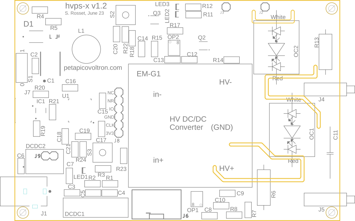
- The silkscreen has labels for all the resistors/capacitors and ICs. With the help of the BOM, solder all surface mount devices and components. Make sure to use the BOM v1.2 rev1, as the revised BOM version contains a few changes of component values that will improve the performance of the hvps-x.
- Screenshots below are for PCB v1.2, but PCB v1.3 on the website is essentially the same from a component layout point-of-view.
- Resistors and capacitors have a 1206 package, which is large and easy to solder. However, there are a few components with small footprints that require some basic soldering skills. We wouldn’t recommend this board as a first soldering experience. If you have never soldered a PCBA before, we suggest you practice on a test circuit first (see additional resources below).
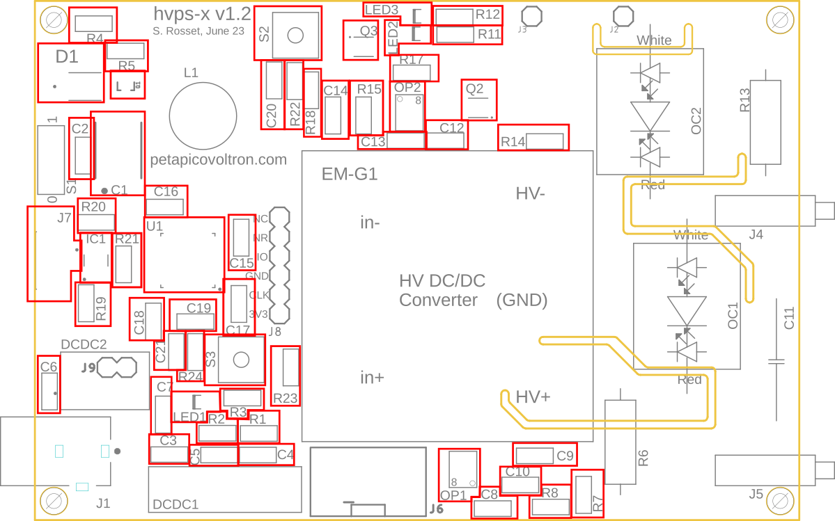
- In this first assembly step, we are only going to solder the SMT/SMD components. They are shown in red in the image below.
| Component | 6kV | 5 kV | 4 kV | Other ratings |
|---|---|---|---|---|
| EMG1 | G60 | G50 | G40 | Contact us |
| R7 | 52.3 kΩ | 64.9 kΩ | 80.6 kΩ | Contact us |
| R14 | 261 kΩ | 316 kΩ | 392 kΩ | Contact us |
- We recommend using a stencil to apply solder paste, and a reflow oven (or a hot air gun) to solder these components. However, it can be done with a soldering iron (see some of the video tutorials below). Even if using a soldering iron, it helps to order a stencil and apply apply paste to the pads. A steel stencil ordered with your PCBs will cost ~10-15 USD. The trickiest component to solder with an iron will be the USB connector, as the pins have limited accessibility.
- Resistors are not polarised, so you don’t need to pay attention when soldering; just make sure you place the correct resistor value at the right location (refer to the BOM). R7 and R14 have values that depend on the voltage rating of the HV DC/DC converter that you will solder later. Refer to the BOM to make sure you place the correct value depending on the output voltage of your HV DC-DC converters. The table above also shows the components that are dependent on the voltage rating of the hvps-x.
- Just one oddity: the R17 location is for a capacitor (refer to the BOM).
- C1 is polarised. The positive terminal (indicated with a band on the package) should be oriented down, where the dot is located on the silkscreen. The other capacitors are not polarised.
- Diode D1’s cathode goes on the left (towards the dot on the silkscreen).
- IC1 (USB ESD protection) pin 1 is on the bottom left (dot on the silkscreen).
- LED 1, 2, and 3 have their cathodes on the left (as indicated by the line on the silkscreen)
- OP1 and OP2 (operational amplifier, have their pin 1 indicated by a hollow circle on the silkscreen. Pin 8 is also indicated with an 8.
- There is a dot indicating the pin 1 of Q2 and Q3, but it is possible that the package has no indication. This is because the chip can be rotated by 180 degrees, and orientation therefore doesn’t matter.
- The orientation of S2 and S3 is not important, they can be rotated by 180° without issue (but not 90°!). If using a reflow oven, we recommend manually soldering S2 and S3 afterwards, as the plastic button is not very heat resistant!
- Pin 1 of the micro-controller (U1) is indicated by a dot (bottom left)
Once you have soldered these components, the difficult part of the assembly is done! This is what you should have at this stage:
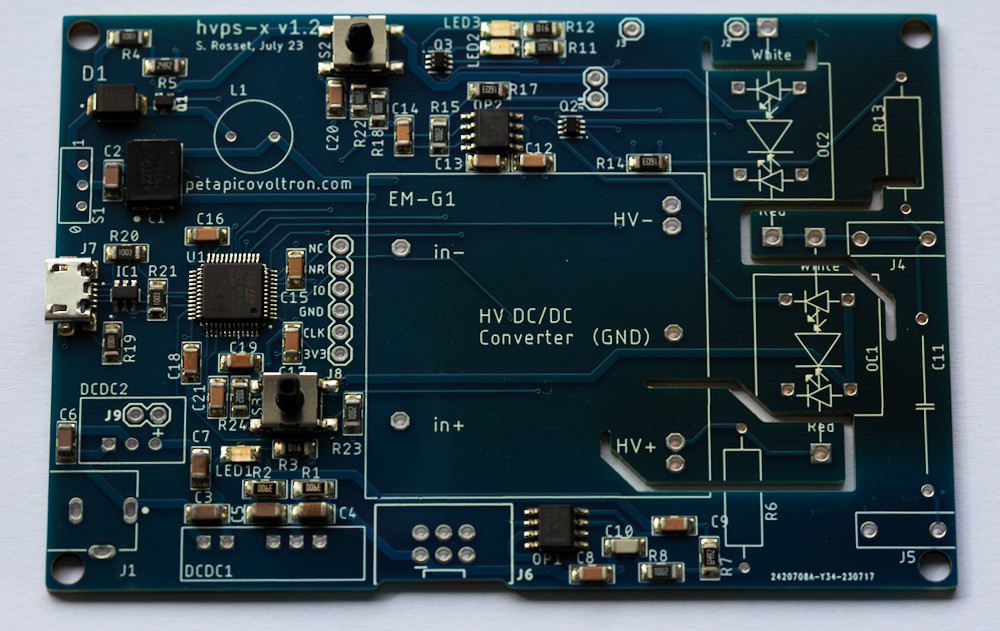
Carefully check the pads of the USB connector, the micro-controller and other ICs under a binocular or with a magnifying glass to make sure there are no solder bridges between pins and that all pins are correctly soldered to their pads.
Additional Soldering Resources
- If you don’t have much practice soldering components, and to avoid damaging the most delicate (and expensive) components, you may want to improve your soldering skills. No need to reach Jedi level, but a bit of dexterity will help. One possibility is to buy some cheap practice kits such as this.
- Learn to solder with Dave from EEVblog. In this video, he’s using solder and the drag method.
- A knife soldering tip works well to solder the microcontroller. Make sure to first solder two diagonal corners to hold it in place.
- And here Dave shows you how to use solder paste and a stencil (which you can order together with the PCB. PCBWay does it for USD 15).
- Using solder paste applied manually Soldering with a hot air gun. Includes re-work to remove solder bridges with a solder iron.
Next step
Once you have soldered the SMT components, the next step is to test the communication with the micro-controller.