The release of hvps-x means the end of development and support for the original SHVPS described on this page. The files and instructions remain accessible, but we won’t provide upgrades or support. The reason for stopping support is that we don’t have any SHVPS left to work on, nor any LabVIEW license to work on the user interface. If you want to assemble a high voltage power supply, we recommend our new hvps-x.
This page describes the main components of the HVPS.
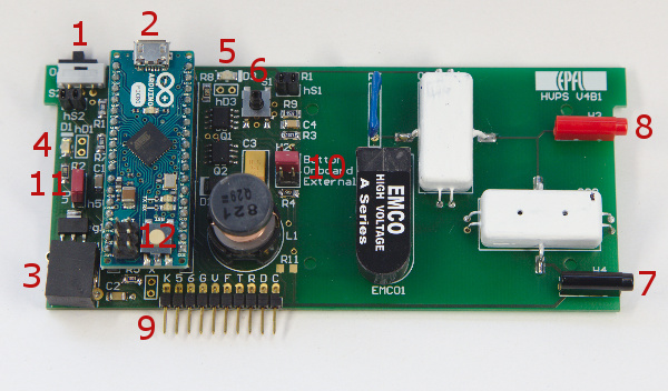
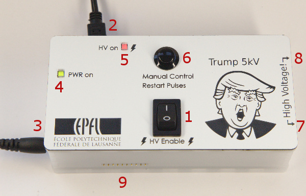
- High Voltage enable switch. This switch controls whether the high voltage generation circuit is powered on . When it is on 0, there is no high voltage present at the output, and the HVPS can be safely handled. The switch should be in the 0 position when manipulating the HVPS, connecting a cable to the output, connecting a device, etc. Only when everything is set-up, should this switch be placed on the 1 position. Communication with the HVPS is possible when the switch is on 0 (i.e. this switch controls the HV side of the HVPS, but the control electronics remain powered up even when the switch is off.)
- USB micro connector. Used to connect the HVPS to a computer.
- Power socket for the 6V D.C. power supply. You need to connect the external power supply if you want to use the HVPS. The USB cable alone makes it possible to communicate with the unit, but the 6V input is necessary to power on the high voltage part of the circuit.
- Power on LED. Indicates when the HVPS is powered up. It turns on when the HVPS is powered via the USB bus (2) and/or the power supply (3). When this LED is turned on, communication with the HVPS is possible. However, this doesn’t mean HV is present at the output. The board can be safely handled when this LED is on, provided the high voltage enable switch (1) position is 0.
- HV LED. This LED turns on when a voltage > 40V is present at the HVPS output. It indicates a potential danger. Do not manipulate wires and connectors when this LED is on! If you have setup the HVPS to output a voltage but the HV LED remains off, check that a) the HV enable switch (1) is in position 1, and that b) the 6V power adapter (3) is plugged in.
- Push button: This button allows to a) manually control the state of the output switch (whether 0V or the high voltage is applied to the output (8), or b) restart a series of pulses.
a) Manual control of the state of the output switch
There are two different settings that allows to use the button to directly control the state of the output switch. Either by placing the jumper on header H2 (10) on the button position (top position), or by placing the jumper to the onboard (central) position, and issuing a command to the HVPS to select the button as the source of switching. This can be done directly through a serial connection via the command SSwSrc 2 (see list of commands for more information), or using the LabVIEW GUI. The button can be programmed with two different behaviours: 1) a push button behaviour: you have to keep the button pressed to have high voltage at the output and 2) a latching switch behaviour: each time you press the button, the state of the output toggles between HV on and off.
b) Restart a series of pulses
When the HVPS is configured to output a square signal, it can be programmed to generate a fixed number of cycles and then stop. The button can be used to restart a series of cycles after it turns off following the execution of the programmed number of cycles. - Ground output connection. 2mm banana socket. Whether it is true ground or not depends on your 6V power adapter and the computer to which the HVPS is connected. We recommend grounding the circuit in case your setup makes that the ground plane of the PCB is floating vs. true ground.
- High voltage output connection. 2mm banana socket
- 10-pins bus. Mainly used when the HVPS is used in multi-channel configuration. However, in single channel configuration, Pin 5 (V) and 6 (F) can be used to set the board output voltage and the state of the output switch respectively.
To use pin 5 (V) to control the programmable HV voltage source output voltage, the HVPS must be configured with external control as voltage setpoint. This can be done directly through a serial connection via the command SVMode 1 (see list of commands for more information), or using the LabVIEW GUI.
Using pin 6 (F) to control the state of the output switch with a TTL signal can be done with two different settings: either by placing the jumper on header H2 (10) on the external position (bottom position), or by placing the jumper to the onboard (central) position, and issuing a command to select the external signal as the source of switching. This can be done directly through a serial connection via the command SSwSrc 1 (see list of commands for more information), or using the LabVIEW GUI. - Switching source header. This header allows to define how the fast switch is controlled. There are 3 different settings. From top to bottom:
–Button: the switch is controlled by the onboard push button. The button can be programmed with two different behaviours: 1) a push button behaviour: you have to keep the button pressed to have high voltage at the output and 2) a latching switch behaviour: each time you press the button, the state of the output toggles between HV on and off. The state of the HV LED (5) does not reflect the state of the output when the jumper is on position button. Its indication should be ignored.
–Onboard: the micro-controller controls the state of the switch. 3 sources are possible: push button, internal timer for switching at a settable frequency, and an external TTL signal. Setting the jumper to the onboard setting gives the most flexibility and is the recommended setting. The switching source can be selected by issuing SSwSrc commands (see list of commands for more information), or using the LabVIEW GUI. The HV LED (5) reflects the state of the output when the jumper is on the onboard position.
–External: the switch is controlled by an external 5V TTL signal applied on pin 6 of the 10-pin header (9). The state of the HV LED (5) does not reflect the state of the output when the jumper is on position external. Its indication should be ignored.
Unless you want to force the switching source to a particular setting via the hardware, it is recommended to leave the jumper on the central position and select the switching source via software. - Power header: This header connects the the power jack (3) to the HVPS. When the HVPS is used as stand alone, this header must be in the on position. This header is placed in the “off” position only when the HVPS is used as a multi-channel configuration.
- Arduino reset button: Three words “Do not press”. This button is not accessible when the HVPS is inside the enclosure. If you need to reset the micro-controller, unplug both the USB cable and the power cord. Pressing on the reset button while the HV enable button (1) is in the 1 position will apply the full voltage to the output for a few seconds!