The release of hvps-x means the end of development and support for the original SHVPS described on this page. The files and instructions remain accessible, but we won’t provide upgrades or support. The reason for stopping support is that we don’t have any SHVPS left to work on, nor any LabVIEW license to work on the user interface. If you want to assemble a high voltage power supply, we recommend our new hvps-x.
Warning! This enclosure design is not compatible with the PCB v6, as the power jack has changed location. Until we provide a modified design, please use the minimal enclosure for the PCB v6.
The full enclosure is a complete box that protects the SHVPS and prevents users from touching the high voltage components. The important functions (buttons and LEDs) are placed on a front panel. In the current versions, the onboard LEDs are used, but transparent light pipes guide the light to the front panel. The two buttons (High Voltage enable and push button) are mounted on the panel. Consequently, in step 18 of the assembly instructions, it is necessary to solder header hS1 and hS2, but headers hD1 and hD3 are not required.
Alternatively, you can also assemble a minimal enclosure which is simpler and easier to assemble. It only covers the HV side of the circuit, and uses the onboard switches and LEDs.

We use a Laser Engraver Trotec Speedy 300 to cut the parts required for the enclosure, and we have prepared files ready to be cut. We also have the Solidworks 3D files, so you can use whatever method you want to cut the parts or modify the enclosure to fit your needs.
Download the Solidworks files (Solidworks 2015)
1. Cutting / Preparing the parts
The enclosure is made of 3 different materials/parts
1.1 Enclosure Body
We use a 3 mm thick opaque PMMA for the main body of the enclosure. The file full_opaque_box.svg contains all of the parts that need to be cut to assemble the main body. You need a plate of at least 150 mm x 280 mm to cut all the parts.

1.2 Front Panel
We use an engravable plastic TRANSPLY-HD with a black body and a white front layer. We use the 1.5mm-thick plates. You can use any other thickness value, but the length of the light pipe (see below) must be adapted accordingly. The file front_panel_model.svg can be used as a base for the front panel.

The black filled shapes are engraved by the laser. The red and blue lines are the cut lines, matching the one on the part “Top”. We recommend that you indicate the name of the HVPS and the voltage rating (Edit the string that says “Name” X kV by the actual name and the voltage rating of your HVPS.) You can use the space below the name to add an image in relation with the name of your HVPS, and there is space for a logo on the bottom left. See illustrative example at the top of the page…
A Laser works very well to engrave the panel, but is not optimal to cut the openings and external shape (ABS is not easy to cut with a Laser, because it melts). We suggest you try one of the following approaches:
- Start by cutting the openings before removing the protective cover on the top. The bits of molten ABS will land on the protective cover and will not stain the panel. Then remove the protective cover and proceed with the engraving step. The disadvantage with this method is that you need to precisely position the panel after cutting it so that the engraving match the geometry. But a very precise alignment is not required anyway.
- Start by removing the protective cover and replace it by masking tape. You can then do the three operation in one go without moving anything and in the logical order (engrave, cut red, cur blue). You must adapt the engraving parameters to go through the masking tape too. Masking tape burns without melting. This is the reason why we replace the plastic cover sheet with masking tape. Finish by removing the masking tape that will have caught the projections creating during the cutting step.
1.3 Light Pipes
The file LED_pipe.svg defines a light pipe used to guide the light from the onboard LED to the front panel. You should be cut two light pipes into a 3mm-thick transparent material (we use PMMA). You need to cut two light pipes (power LED and HV LED). The file as designed is for a front panel (see previous §) thickness of 1.5 mm. If you use another thickness for the front panel, you should adapt the length of the light pipe. It is a good idea to sand the top of the light pipe to diffuse the light of the LED on the front panel
2 Assembling the parts
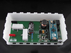
- Using glue for plastics (we use dichloromethane), assemble together the following parts (see picture below): base, side_hv, side_hv_cache, side_jack and back.

Base: Place the larger 3 openings on your left.
Back: The slit must be at the bottom right.
Side_jack: On the right. The straight side (without slots) towards the front.
Side_hv: On the inside left. The straight side (without slots) towards the front.
Side_hv_cache: On the outside left. The straight side (without slots) towards the front. - You can slide a HVPS to check that everything is correctly positioned.
- Place M2 threaded metallic inserts (Tappex Multisert – Single Thickness Head – 071M2) in the parts holder and holder2.
Note: You can replace the inserts by a threaded hole. In that case, you must modify the diameter of the holes on these parts to 1.5mm prior to cutting the parts.

- Glue the following parts (see picture below): top, holder and the two holder2.
Place top so the rectangular opening is in front of you, and the 2×3 openings on your left (see image). holder goes on the left, and the two holder2 on the right. The flanges from the inserts (not shown on the picture) should be located on the inside.


- Place double sided tape (or glue) on the top of the front panel.
The two large openings for the two buttons, as well as the 2 small square openings for the diode lightpipes must remain free from tape.

- Place the engraved front panel on top of the tape-covered top part.
Carefully align the two parts. It may help to first place the large switch in the engravable panel, and use it as a guide. The two lightpipes can also be used to add guiding posts to perfectly align the two pieces together. Apply pressure to fix the two parts together. - If not already done so at the previous step, insert the switch in the square opening.
Order code: Farnell 4710368
Part number: PRASA1-16F-BB0BW
Description: TE CONNECTIVITY / ALCOSWITCH PRASA1-16F-BB0BW Rocker Switch, Non Illuminated, SPST, On-Off, Black, Panel, 16 A - Insert the push-button in the round opening.
Order code: Farnell 1634622
Part number: R13-502A-05-B
Description: MULTICOMP R13-502A-05-B Pushbutton Switch, Off-(On), SPST, 125 V, 3 A, Solder - Insert the two light pipes in the small square openings and glue them in place from the backside.
- Solder wires to the the switch and push button.
The wires for the switch should be 110 mm long.
The wires for the push button should be 60 mm long.
Take a wire to board connector and cut two units of two pins. Solder one unit at the extremity of each of the cables.
Order code: Farnell 9729100
Part number: SL 3.25.36G
Description: FISCHER ELEKTRONIK SL 3.25.36G Wire-To-Board Connector, Right Angle, SL Series, 36 Contacts, Plug, 2.54 mm, Through Hole, 1 Rows
The picture below illustrates steps 7-10

- Connect the wire from the push button to header hS1. Cut the wire-to-board connector of the switch to separate the two contacts, and insert the contacts into header hS2.
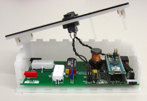
The wire from the switch should go along the Arduino and between the edge of the Arduino and the power jack in the back, as shown on the image above. The two contacts should be inserted sideways into header hS2, as shown in picture below so that the wire doesn’t cover the onboard LED D1, or else you won’t be able to place the cover with the light pipe (see image below).

- Place the side panel (part front-removable).
The onboard switch S2 must be in the 0 position. There is a notch in the front-removable part that prevents you from placing the part when the switch is not in the correct position.

- Place the front panel in place, and lock it in place with 4 plastic M2x10 screws.