The release of hvps-x means the end of development and support for the original SHVPS described on this page. The files and instructions remain accessible, but we won’t provide upgrades or support. The reason for stopping support is that we don’t have any SHVPS left to work on, nor any LabVIEW license to work on the user interface. If you want to assemble a high voltage power supply, we recommend our new hvps-x.
The testing procedure should be printed, marked and added to the other testing documents.
Report the name and I2C address from the low-voltage test sheet.
Name of testing agent:_______________________________________________________
Date:___________________________________________________________________
Board Name:______________________________________________________________
I2c Address:_______________________________________________________________
Test of the micro-controller
- Take a Arduino micro, but do not install it on the HVPS PCB.
- Open the Arduino IDE (you must have the Arduino IDE installed, as well as the required drivers for the serial communication. Refer to this page for more information)
- Program the Arduino with the Send_PWM program.
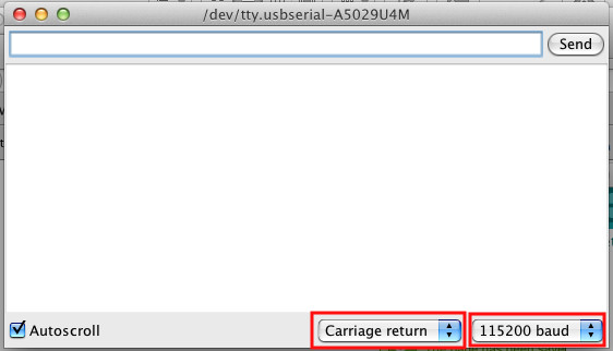
- In Arduino GUI, open the Serial Monitor.
- Set the termination character to “Carriage return” and the transmission speed to “115200” in the 2 dropdown lists.
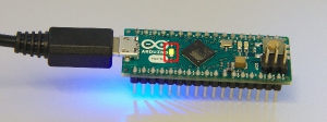
- Check that the the onboard LED (green) is fully on
☐ Onboard LED is on
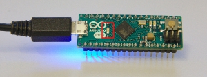
- In the serial monitor, enter 0 and press enter. The green LED should turn off, and the terminal should indicate:
PWM set point: 0
ADC read XXX
(the value of XXX is not important at this stage)
☐ Expected values are displayed on the terminal
☐ Onboard LED is off
- In the serial monitor, enter 1023 and press enter. The green LED’s intensity should be at 100%, and the terminal should indicate:
PWM set point: 1023
ADC read XXX
(the value of XXX is not important at this stage)
☐ Expected values are displayed on the terminal
☐ Onboard LED is on

- Close serial monitor, and unplug the USB cable from the Arduino.
Testing the High Voltage
Be Careful when testing the high voltage part of the circuit, as the board is not yet in a protective enclosure. High voltage will be present at the output and on some of the components during the testing of steps 6 and 7. It is important not to touch any part of the SHVPS during this test, and to place the PCB on a well-insulated surface.
- Insert the micro-controller into socket UC1 of the HVPS board, with the USB connector aligned with the PCB overlay
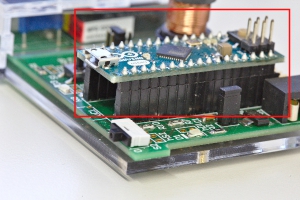
- Be sure that the HV enable switch (S2) is in the 0 position
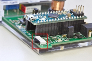
- Plug the USB cable to the microcontroller
- Open the serial monitor in the Arduino interface (the end character and speed settings should be CR/115200, see above)
- Place HV enable switch (S2) on 1
- On serial monitor, enter 0 and press enter. Write the reading from the ADC:
ADC Read: ___________________
☐ ADC Read is higher than 850 and smaller than 1023 - On serial monitor, enter 500 and press enter. Write the reading from the ADC:
ADC Read: ___________________
☐ ADC Read is higher than 200 and smaller than 1023 - On serial monitor, enter 1023 and press enter. Write the reading from the ADC:
ADC Read: ___________________
☐ ADC Read is smaller than 10. If not, try step 8 once again. - Close serial monitor
- Place HV enable switch (s2) on 0
- Remove USB cable
Next Steps
- Place the jumper of header H2 in the central (onboard) position if you want to use the board with the GUI. If you want to force the use of the push button or the external pin as switching source, you can place the jumper on the appropriate position
- Check that the jumper of the header h5V is in the ‘on’ position
- Continue with the calibration of the board, and the fabrication of the enclosure.
