The release of hvps-x means the end of development and support for the original SHVPS described on this page. The files and instructions remain accessible, but we won’t provide upgrades or support. The reason for stopping support is that we don’t have any SHVPS left to work on, nor any LabVIEW license to work on the user interface. If you want to assemble a high voltage power supply, we recommend our new hvps-x.
The following testing procedure should be printed and marked for debugging and record keeping.
Name of testing agent:
Date:
Model (kV):
Board Name*:
I2C Address*:
*Assign a name and a I2C address to your board. The name and address will be stored at a later stage in the micro-controller. The name helps differentiate different HVPSs, and because they all have their own personality, and maximal voltage, we like to give them a distinctive name. The I2C address is used if you want to assemble several HVPS into a multi-channel high-voltage power supply (MHVPS). Valid addresses are between 10 and 127.
- Check all the resistor values. Place a tick in the box if the marking on the resistor matches the value below.
☐ R1 = 27R0
☐ R2 = 1500
☐ R3 = 1001
☐ R4 = 27R0
☐ R5 = 1001
☐ R7 = 1001
☐ R8 = 1500
☐ R9 = 9532 (5kV model)
☐ R9 = 8062 (3kV model)
☐ R9 = 1203 (2kV model)
☐ R9 = 8872 (1.2kV model)
☐ R9 = 2153 (500V model)
☐ R10 = 1001
☐ R11 = 1002 - Check the polarity of the components below. Place a tick in the box if the polarity matches the polarity on the PCB overlay.
☐ D1
☐ D2
☐ D3
☐ C3
☐ Q1
☐ Q2
☐ OC1
☐ OC2 - Measure the resistance between the 5V rail and GND.
How to conduct test: Use the dummy microcontroller and install it on the HVPS PCB as shown on picture below (note that the side with the outline of the USB connector (two short vertical lines) goes towards the top of the PCB, and the side with the switch s1 goes towards the bottom side of the board) With a multimeter, measure the resistance between the test points labelled ‘5V’ and ‘GND’ on the dummy microcontroller.

Purpose of test: To determine if there are any shorts between the power rails before applying power.
Resistance between red and black wire (Jumper h5V should be in the on position at this stage): [divider_flat]
☐ Resistance is approximately 900Ω – 1.1kΩ - Measure the output of the 5V regulator.
How to conduct test:
*Leave the dummy microcontroller connected for this test*
a) Place the jumper h5v in the OFF position
b) Plug in the 7.5V adapter.
Order code: Digikey 237-2156-ND
Part number: WSX075-3200-13
c) Measure the voltage of the regulator relative to ground. Use the ‘GND’ test point on the dummy microcontroller to connect to ground, and probe the large tab of Reg1 with a multimeter probe. Record the voltage below.

Purpose of test: To determine if the regulator is functioning correctly without the remainder of the circuit connected.
Voltage with jumper h5v in the OFF position:
☐ Voltage is approximately 5V - Test if the circuit has power.
How to conduct test:
*Leave the dummy microcontroller connected for this test*
a) Place the jumper h5v in the ON position
b) Observe D1
c) If LED D1 glows green, place a tick the check box and continue. If not, remove the jumper and investigate for a cause.

Purpose of test: To determine if there are any components which are consuming too much power due to assembly errors or faulty components.
☐ D1 glows green - Test the power pin on the microcontroller header and the HV indicator LED
How to conduct test:
*Leave the dummy microcontroller connected for this test. Leave the power adapter connected for this test. Leave the power jumper in the ON position*
b) On the dummy microcontroller, ensure that the switch S1 is in the ‘D3’ position.
c) Observe the LED on the dummy microcontroller. If the LED glows, place a tick in the box below. If not, remove the power jumper (h5v) and check for a cause.
d) Observe LED D3. If LED D3 glows red, place a tick in the box below. If not, remove the power jumper (h5v) and check the polarity of LED D3.

Purpose of test: Step c) tests whether the power pins on the microcontroller are connected to power. Step d) tests if the HV indicator LED is functional.
☐ The LED on the dummy microcontroller glows orange
☐ LED D3 glows red when the switch is in the ‘D3 test’ position - Check if the high frequency switching circuit is functioning correctly
How to conduct test:
*Leave the dummy microcontroller connected for this test. Leave the power adapter connected for this test. Leave the power jumper in the ON position*
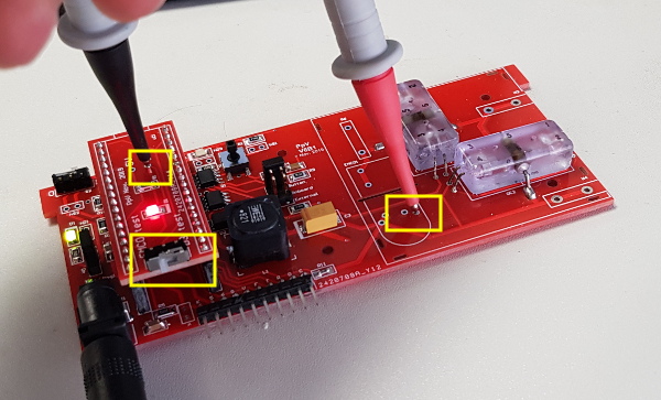
a) Place a jumper on H2 in the ‘Button’ position.
b) Connect the COM port of the multimeter to the GND test point of the dummy microcontroller.
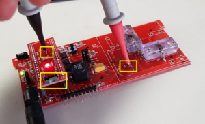
c) Using a probe measure the voltage of the via close to R4. Record the voltage when push button S1 is depressed and when pressed.

Purpose of test: This test measures the output from Q1. The voltage must toggle from rail to rail to turn the infrared LEDs on and off.
Voltage on via close to R4 when S1 is depressed:
☐ voltage on via is ~5V when button is depressed
Voltage on via close to R4 when S1 is pressed:
☐ voltage on via is ~0V when button is pressed - Check all the components powering the EMCO DC-DC converter
How to conduct test:
*Leave the dummy microcontroller connected for this test. Leave the power adapter connected for this test. Leave the power jumper in the ON position*
a) Place the safety switch S2 in the On position (indicated on the board with a small ‘1’ to the right of the switch)
b) Ensure that the COM port of the multimeter is still connected to the GND wire of the rail board.
c) Place the switch on the dummy microcontroller into the ‘EMCO’ position
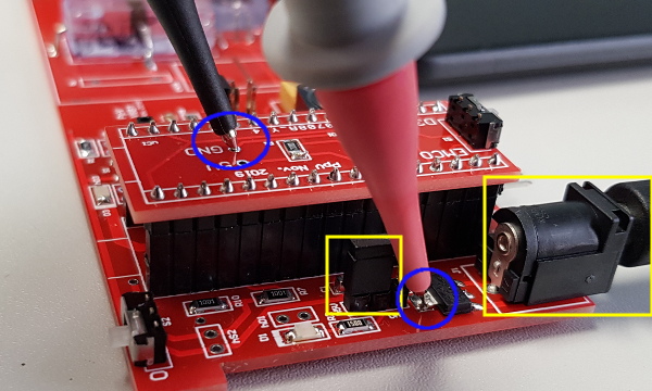
d) Using a probe measure the voltage on the EMCO control pin (see picture: GND probe on the GND connection of the dummy microcontroller, and positive probe on one of the two pads at the bottom right of EMCO1) and record the value below.
e) Place the switch on the dummy microcontroller into the ‘D3 test’ position
f) Using a probe measure the voltage on on the EMCO control pin (see picture: GND probe on the GND connection of the dummy microcontroller, and positive probe on one of the two pads at the bottom right of EMCO1) and record the value below.
Purpose of test: To test if the circuit providing power to the EMCO is able to provide 5V.
Voltage on pin pair 2-5 when switch is in ‘EMCO test’ position:[divider_flat]
☐ voltage on pin pair 2-5 is ~5V when the switch is in EMCO test position
Voltage on pin pair 2-5 when switch is in ‘D3 test’ position:[divider_flat]
☐ voltage on pin pair 2-5 is drifting towards zero when the switch is in D3 test position


If your HVPS has passed all the low voltage tests above (all check boxes ticked), you can continue with the soldering of the high voltage components (section 4 of the assembly page).