The release of hvps-x means the end of development and support for the original SHVPS described on this page. The files and instructions remain accessible, but we won’t provide upgrades or support. The reason for stopping support is that we don’t have any SHVPS left to work on, nor any LabVIEW license to work on the user interface. If you want to assemble a high voltage power supply, we recommend our new hvps-x.
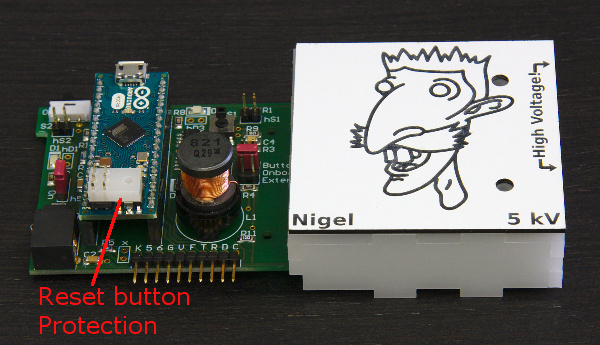
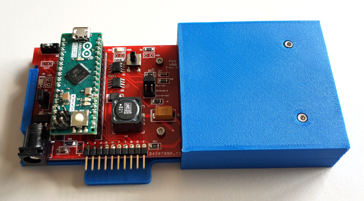
The minimal enclosure is a somewhat simpler enclosure than the full enclosure. It is therefore quicker to make and to assemble. Only the high voltage side of the circuit is protected, leaving the low-voltage side exposed, for easy access to the onboard buttons and LEDs. The minimal enclosure leaves the microcontroller exposed. Accidentally pressing the reset button on the microcontroller while the HVPS is in use leads to the transient application of the full voltage at the output. Consequently, a reset button protection is placed on the microcontroller to avoid undesired activation of the reset button.
1 Minimal Enclosure with 3D printer
The easiest way to make the enclosure is to use a 3D printer. The Download page has a zip file containing the required STL files (3D_printing_minimal_enclosure.zip). We have tested the files with an Ender 5 FDM printer, but it should work with any printer. There is a based and a cover that can be clipped together. However, we also recommend to secure the PCB to the base and the cover to the base using screws. The base part has 5 posts, 4 of which have holes. The holes are design to accommodate a M2 metallic insert, such as this. However, the design can modified, and the hole diameter reduced to be tapped for an M2 screw. 2 screws M2x6 are used to hold the PCB on the base, and 2 screws M2x16 are used to lock the cover.
2 Minimal Enclosure with a Laser cutter
We use a Laser Engraver Trotec Speedy 300 to cut the parts required for the enclosure, and we have prepared files ready to be cut. We also have the Solidworks 3D files, so you can use whatever method you want to cut the parts or modify the enclosure to fit your needs.
Download the Solidworks files (Solidworks 2015): Download page –> Enclosure Files –> minimal_enclosure_Solidworks_files.zip
2.1 Enclosure Body
We use a 3 mm thick opaque PMMA for the main body of the enclosure. The file Download –> Enclosure Files –> minimal_enclosure.svg: contains all of the parts that need to be cut to assemble the main body. You need a plate of at least 220 mm x 100 mm to cut all the parts.
2.2 Front Panel
We use an engravable plastic TRANSPLY-HD with a black body and a white front layer. We use the 1.5mm-thick plates. The file Download –> Enclosure Files –> minimal_enclosure_front_panel_model.svg can be used as a base for the front panel.

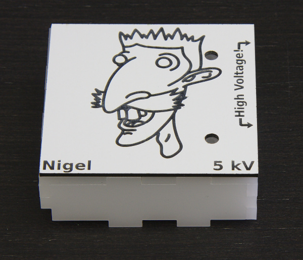
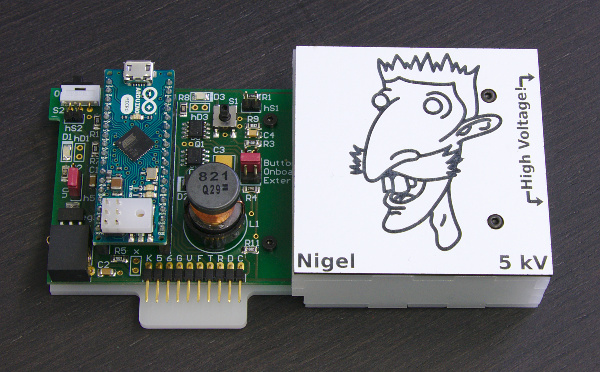
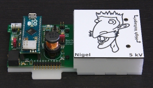
The front panel is optional. It only provides text indication of the HVPS name and voltage rating.
The black filled shapes are engraved by the laser. The red and blue lines are the cut lines, matching the one on the part “Top”. We recommend that you indicate the name of the HVPS and the voltage rating (Edit the string that says Box name xx kV by the actual name and the voltage rating of your HVPS.) You can use the free space to add an image in relation with the name of your HVPS. See illustrative example at the top of the page…
A Laser works very well to engrave the panel, but is not optimal to cut the openings and external shape (ABS is not easy to cut with a Laser, because it melts). We suggest you try one of the following approaches:
- Start by cutting the openings before removing the protective cover on the top. The bits of molten ABS will land on the protective cover and will not stain the panel. Then remove the protective cover and proceed with the engraving step. The disadvantage with this method is that you need to precisely position the panel after cutting it so that the engraving match the geometry. But a very precise alignment is not required anyway.
- Start by removing the protective cover and replace it by masking tape. You can then do the three operation in one go without moving anything and in the logical order (engrave, cut red, cur blue). You must adapt the engraving parameters to go through the masking tape too. Masking tape burns without melting. This is the reason why we replace the plastic cover sheet with masking tape. Finish by removing the masking tape that will have caught the projections creating during the cutting step.
2.3 Assembling the parts
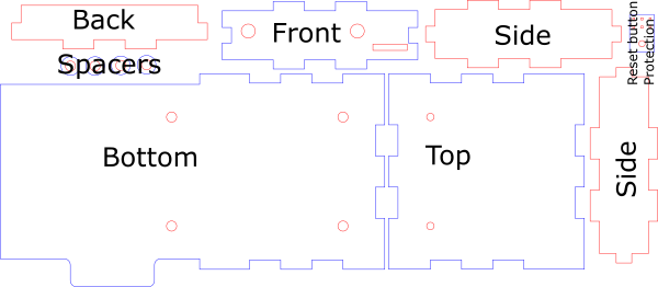
- Using glue for plastics (we use dichloromethane), assemble together the following parts (see picture below): Back, Front, Side (2x), Top.

Pay attention to the position of the holes in the top part, which must be on the side of the front part. Also note the orientation of the slit in the front part, as indicated on the picture. - Place double sided tape on the topside of the top part (do not cover the 2 holes), and position the engraved front panel.

- Slide the PCB into the cover, so that the PCB tab slides into the slit of the front part. Insert the Reset protection on the ICSP header of the microcontroller to avoid undesired activation of the button.

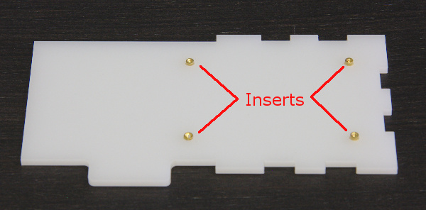
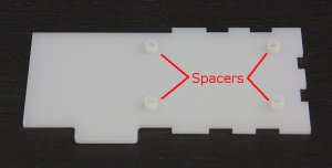
- Insert the 4 M2 inserts into the bottom part

Alternatively, you can also tap the holes with a M2 thread, but you need to adapt the diameter of the holes before cutting the part. - Place the 4 spacers on top of the inserts
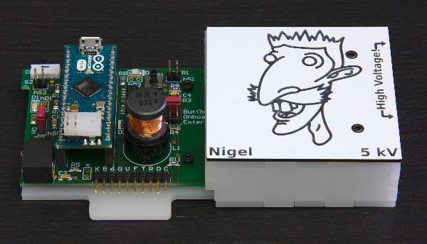
- Place the PCB with the cover on top of the bottom part with spacers, and lock lock it in place with screws.
You need 2 M2x6mm screw on the left, and 2 M2x20mm screws on the wight to go through the cover.