The release of hvps-x means the end of development and support for the original SHVPS described on this page. The files and instructions remain accessible, but we won’t provide upgrades or support. The reason for stopping support is that we don’t have any SHVPS left to work on, nor any LabVIEW license to work on the user interface. If you want to assemble a high voltage power supply, we recommend our new hvps-x.
Back to the HVPS User Interface
If you want to control manually the output of the HVPS using the push button located on the board or on the enclosure, use the following configuration:

- Switching source set to button.
- Voltage control mode: internal regulated control (this leads to accurate output voltage, according to the calibration file of the HVPS). You can change voltage control mode (4) only if the voltage set point (5) is 0V, and the source output (1) is off. It should be kept on regulated except for very specific applications.
- Set the desired voltage with either the knob control(3a), or the digital control (3b).
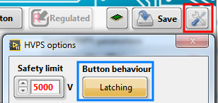
There are two different behaviour for the push button: latching (switch mode) or non-latching (push-button mode). The button behaviour can be set using the HVPS option button (red square in image below), and then selecting latching or non-latching mode using the Button behaviour control (blue rectangle in image below).
Latching (switch) mode:
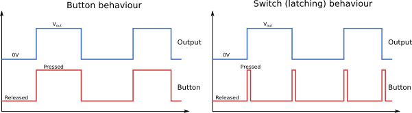
In this mode, the button on the PCB (s1) or on the enclosure panel acts like a switch: the state of the output (on at the programmed voltage/off) can be toggled by pressing and releasing the button. Press and release once to turn the output on. Press and release again to turn the output off.
Non-latching (push-button) mode:
In this mode, the output is on when the button is pressed, and off when it is released. You need to keep the button pressed to keep the output on.
The two different behaviour are illustrated in the figure below.
When the output is controlled manually using the button (switching source set to button as illustrated in the first image above with 1.), the GUI doesn’t know if the output voltage is on or off. Consequently, and as a safety precaution, the GUI HV indicator will be permanently turned on to warn the user that high voltage can potentially be present at the HVPS output. The onboard red HV LED (d3) however indicates the true state of the output. It will indicate whether the input is on or off, which is especially useful when the button mode is set to latching.
When the output is controlled manually using the button (switching source set to button as illustrated in the first image above with 1.), the main controls of the GUI On/Off, as well as DC/Switching/Waveform have no effect. The signal is directly controlled by the button.