The release of hvps-x means the end of development and support for the original SHVPS described on this page. The files and instructions remain accessible, but we won’t provide upgrades or support. The reason for stopping support is that we don’t have any SHVPS left to work on, nor any LabVIEW license to work on the user interface. If you want to assemble a high voltage power supply, we recommend our new hvps-x.
up one level to HVPS User Interface
1 Connection to the HVPS
Connect the HVPS to the 6VDC power adapter and to a computer with the USB cable (refer to setting up the HVPS).
Open HVPS_interface_vx.x.exe (for PC) or OSX_HVPS_interface_vx.x.app (for mac). If it fails to open, or if the HVPS doesn’t appear in the interface, please be sure you have all the required drivers and software components (see Interface installation and prerequisites).
- If no HVPS is connected to the computer, a small connection box shows that no HVPS is available (see picture below, left)). You can hot-plug your HVPS if you forgot to do so before launching the interface. If your HVPS is plugged in, but the interface says No HVPS available, be sure you have all the required drivers and software components (see Interface installation and prerequisites).
- If more than one HVPS are connected, the connection box displays a drop-down list of available HVPS (picture below, right). You can select the one you want and then press on the Connect button. It is possible to connect to more than one
HVPS simultaneously.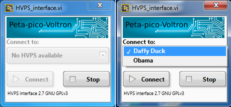
Left: connection box displayed if no HVPS is connected/recognized. Right: connection box displayed if more than one HVPS are connected. - If a single HVPS is connected to the computer, the connection dialogue box is not shown, and communication is automatically initiated with the connected device.
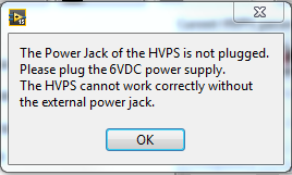
If you forget to plug the power adapter, a dialogue box pops up to remind you to do so. Plug the 6VDC adapter and close the dialogue box.
The following screenshot shows the interface once the communication with two HVPS is established. The connection dialogue on the left shows no HVPS to connect to, as communication has already been established with the two HVPS connected to the computer. Pressing the disconnect button on the interface of each HVPS (bottom right) makes it possible to close the communication with this unit and makes it available again in the connection dialogue. Pressing the Stop button of the connection dialogue closes all open interfaces.
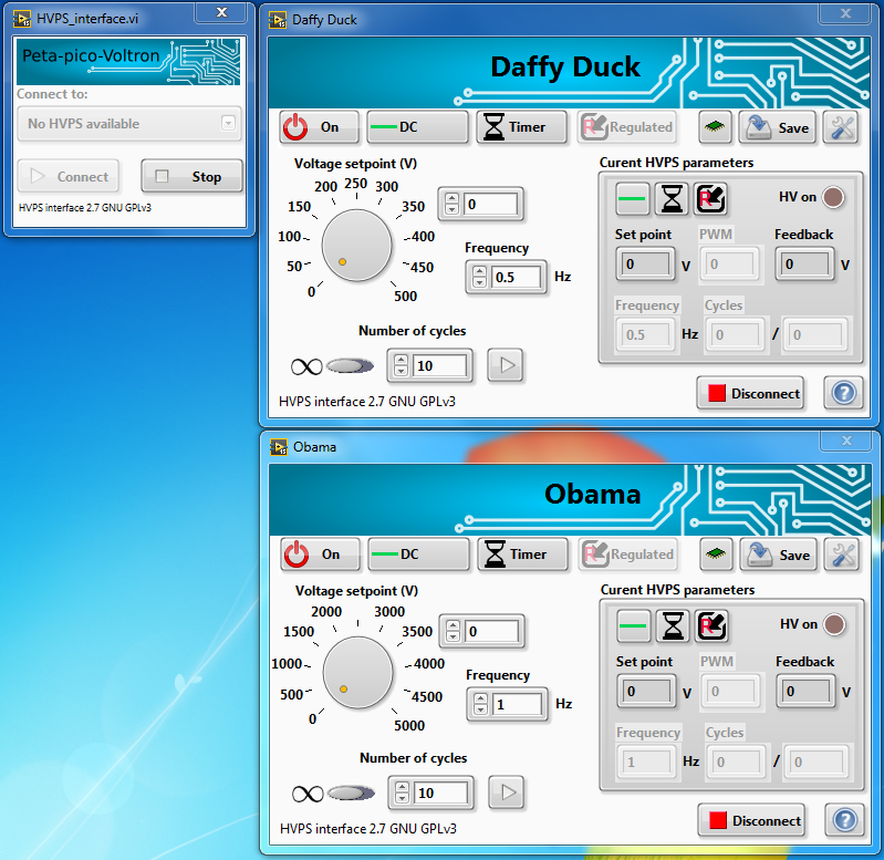
The left part of the interface are the controls to change the settings of the HVPS. The central part, named current HVPS parameters indicates the current setting of the HVPS. Changing a control on the left side should be matched by a change of the indicator on the right side, showing that the HVPS has correctly accepted your command. The commands are accessible at all time. For example, you can set the frequency, even when the HVPS is in DC mode. It has no direct effect, but when you change to switching operation, the frequency that you previously entered is applied. The indicators on the current HVPS parameters part of the interface are greyed out when the HVPS is in a mode in which this particular indicator is not applicable. For example, in DC mode, the indicators Frequency and Cycles are disabled.
2 Context help
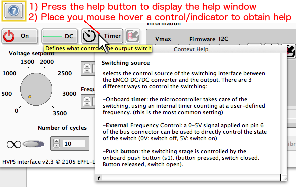
The description of the controls and indicators of the interface is included in the program itself. Hovering the mouse over a field displays a short tooltip. For a more detailed explanation, the help button located at the bottom right of the interface displays a help window with additional explanation on the different elements.
3 On/Off buttons
There are two on/off buttons:
- The hardware on/off switch (or high voltage enable) (Switch S2 on the PCB) which directly acts on the high voltage DC/DC converter. It is a purely mechanical switch: when it is in the position 0, it is physically impossible to have high voltage at the output of the HVPS. The switch should be on 0 when the HVPS is manipulated, or to connect a device to the output leads. Once everything is connected, you can safely place this switch on position 1.
- The GUI on/off button located at the top left of the interface. Pressing this button makes it possible to quickly change from no output, to the programmed output (DC, square signal, …). Pressing the space bar when the interface window has the focus toggles the state of this button, allowing the user to quickly turn the HVPS on/off by one keyboard key press. This is a software button. In case of a communication problem with the HVPS, or other unforeseen event, the output may not reflect the position of this switch. Consequently, even if this button is on the off position, you must also place the hardware switch S2 (High Voltage enable) on 0 before manipulating the output leads.
This means that to have high voltage at the output of the HVPS, 4 conditions must be met:
- The 6 VDC power jack must be plugged
- The hardware switch s2 must be in position 1
- The software on/off switch must be on
- A voltage set point higher than 0 must be defined