We have performed measurements of the current transfer capabilities of the OPTO-150 optocoupler used as output stage of the hvpx-x. The current capability of the optocoupler determines how much current the power supply can deliver. The current output capability is a trade-off between safety and how fast the power supply can charge electrostatic actuators.
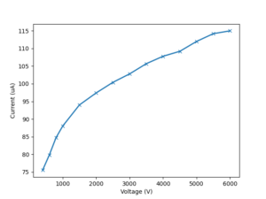
The graph above shows how much current flows through the Optocoupler as a function of the voltage across the diode. This is measured when the optocoupler is activated (i.e. IR LEDs on) with the same current as on the hvps-x circuit. The current output of the hvps-x therefore depends on the voltage difference between the output of the high-voltage DC/DC converter, and the output of the hvps-x.
For example, charging an empty capacitor @5kV would initially occur with a current of 110 uA, but the current will reduce as the capacitor charges, and the voltage across the optocoupler reduces. In addition, part of the current delivered by the optocoupler is used by the current-monitoring circuit. As this is a resistor (250MOhm in the current BOM; will be increased to 500MOhm in the next revision), the current used in the monitoring circuit is proportional to the voltage of the load connected to the hvpx-x. To estimate how fast a capacitor of a given size (i.e. an electrostatic actuator) would charge, I have programmed a rather crude finite differences scheme to take into account the current output of the optocoupler as shown above, and the current used in the voltage monitoring circuit. The script is available here (rename the file from .txt to .py).
Let’s look at a few examples:
To researchers who ordered a hvps-x, I have sent characterisation measurements of the output of the hvps-x with some representative loads connected to the output.
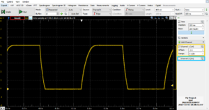
The trace above is measured with a 1:1000 high voltage probe that has an input impedance of 100MOhm. This impedance appears in parallel with the internal 250MOhm voltage measurement circuit, for an effective 70MOhm of output impedance. Using this value as monitoring resistance in the finite difference script, here is the calculated charging profile:
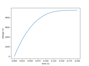
One sees that the calculation predicts it will take ~150ms to reach 5kV, which matches the measurement.
Because of the probe’s impedance, this measurement is not very representative of how fast the the hvps-x can charge a 1.4nF capacitor, as a large fraction of the current capability of the hvps-x is wasted in the probe rather than used to charge the capacitor. With the finite difference script, it is easy to re-calculate the charging profile if the probe was disconnected: we simply need to change Rmonitor to Rmon=250MOhm (i.e. remove the probe impedance in parallel from the voltage measurement circuit). This is what we get (I have also changed the target voltage to 4kV for reasons that will become evident in the next section):
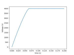
As shown in the figure, the capacitor charges much faster once the probe is removed. The calculation predicts that it will take ~75ms to charge the 1.4nF capacitor to 4kV. This means that we should be able to charge a 1.4nF actuator to 4kV and discharge it is 150ms, or at ~6.5Hz.
Can we check if this is achievable, since measuring the output requires a probe, and the probe has a non-negligible current draw? Yes we can, using a new feature of the GUI (this is not yet released, but will be soon): The trace mode enables to sample the voltage quickly on the hvps, and transmit the arrays of values to the GUI for display on the live graph. This enables displaying values sampled as fast as every 2ms on the GUI graphs, while the normal mode only provides a 2Hz refresh rate). I have a 4kV hvps-x around, so let’s connect a 1.4nF to its output and have it generate a 4kV square wave at 6.5 Hz. If all goes well, we should see that we are able to charge the load capacitor to 4kV during half of the period:
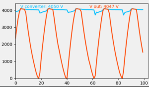
And yes, it works! The finite different script can be used to estimate how fast an actuator of a known capacitance will charge to a target voltage. You can use it to define how fast you will be able to drive your actuators.
(The 1.4nF load value taken as example here would represent a dielectric elastomer actuator of ~26 square centimetre of surface if the membrane thickness is 50 um)
